
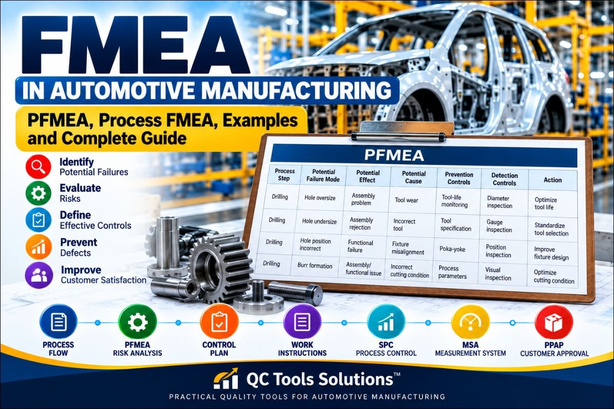
FMEA in Automotive Manufacturing: PFMEA, Process FMEA, Examples and Complete Guide
Failure Mode and Effects Analysis (FMEA) is a systematic and preventive quality management tool used to identify potential failures, understand their effects and causes, evaluate risks, and define actions to reduce or eliminate those risks.
FMEA is widely used in the automotive industry because automotive products involve complex designs, manufacturing processes, machines, tooling, inspection systems, suppliers and customer requirements. A failure at any stage can result in rejection, rework, customer complaints, warranty problems, safety concerns or loss of customer satisfaction.
For manufacturing organizations, Process FMEA (PFMEA) is particularly important because it helps identify potential failures in manufacturing and assembly processes and establish appropriate prevention and detection controls.
This article explains FMEA and PFMEA in a practical way, including types of FMEA, inputs, process steps, Severity, Occurrence, Detection, practical PFMEA examples, Control Plan linkage, review criteria, common mistakes and the relationship between traditional FMEA and the AIAG & VDA methodology.
Note: This article provides an overall understanding of FMEA and PFMEA. For detailed information about the AIAG & VDA 7-step methodology, Action Priority and the new FMEA format, refer to our dedicated article on AIAG VDA Process FMEA.
What is FMEA?
FMEA stands for Failure Mode and Effects Analysis.
It is a structured method used to identify potential failures before they occur and evaluate what can be done to prevent or control them.
The basic logic of FMEA can be understood as:
Process or Product → Failure Mode → Effect → Cause → Controls → Risk → Action
For example, consider a CNC drilling operation.
A possible failure mode may be:
Hole diameter oversize
The effect could be:
Improper assembly or functional problem
A possible cause could be:
Tool wear
The organization may have:
Prevention Control: Tool-life monitoring
Detection Control: Hole diameter inspection
FMEA helps the team evaluate whether these controls are adequate and whether additional actions are required.
The objective of FMEA is not simply to prepare a document for an audit or customer. A properly implemented FMEA should help an organization prevent problems, improve process controls, reduce risk and capture lessons learned.
Why is FMEA Important in Automotive Manufacturing?
Automotive manufacturing requires consistent product quality and stable processes. Even a small process variation can sometimes result in a significant product or customer problem.
FMEA helps organizations identify risks systematically instead of waiting for failures to occur.
Major benefits of FMEA include:
- Identification of potential failures before production problems occur
- Reduction of process and product risks
- Improved prevention controls
- Improved detection controls
- Reduction in rejection and rework
- Better understanding of manufacturing processes
- Support for Control Plan development
- Improved cross-functional communication
- Capture of lessons learned
- Support for continuous improvement
- Better preparation for new product and process launches
- Improved customer satisfaction
FMEA is especially useful during new product development, process development, process changes and problem-solving activities.
It should also be reviewed whenever new information becomes available.
Types of FMEA
FMEA can be applied to different stages of product and process development. The major types relevant to automotive organizations include DFMEA, PFMEA and FMEA-MSR.
Design FMEA – DFMEA
Design FMEA focuses on potential failures associated with product design and design requirements.
For example, consider an automotive bracket.
A potential failure mode could be:
Bracket cracks during vehicle operation
The team evaluates the possible effects, causes, existing design controls and actions required to reduce the risk.
DFMEA is therefore primarily concerned with product and design-related risks.
Process FMEA – PFMEA
Process FMEA focuses on potential failures associated with manufacturing and assembly processes.
PFMEA considers:
- Process steps
- Process functions
- Potential failure modes
- Effects of failures
- Potential causes
- Prevention controls
- Detection controls
- Risk
- Improvement actions
For automotive component manufacturers, PFMEA is an important tool for systematic process-risk analysis.
FMEA-MSR
FMEA-MSR refers to FMEA for Monitoring and System Response.
It addresses risks associated with monitoring and system response during vehicle operation.
The AIAG & VDA FMEA methodology provides guidance for Design FMEA, Process FMEA and FMEA-MSR.
For detailed information about AIAG & VDA FMEA, refer to your dedicated AIAG VDA FMEA article rather than duplicating the complete methodology here.
Difference Between FMEA and PFMEA
FMEA is the broader failure-analysis methodology, while PFMEA specifically focuses on manufacturing and process risks.
| FMEA | PFMEA |
|---|---|
| Failure Mode and Effects Analysis | Process Failure Mode and Effects Analysis |
| General risk-analysis methodology | Manufacturing/process-focused methodology |
| Can be applied to different areas | Mainly focuses on manufacturing and assembly |
| Includes different FMEA applications | One specific application of FMEA |
| Identifies potential failures and risks | Identifies process-related failures and risks |
In simple terms:
PFMEA is a specific application of FMEA for manufacturing processes.
Purpose of PFMEA
The primary purpose of PFMEA is to identify potential process risks before they result in defects or customer problems.
A good PFMEA should help the team answer:
- What is the process supposed to do?
- What could go wrong?
- What would happen if it went wrong?
- Why could the failure occur?
- How can the failure be prevented?
- How can the failure be detected?
- What is the associated risk?
- What actions are required?
- Who is responsible for the action?
- How will the effectiveness of the action be verified?
The answers should be based on actual process knowledge and available data wherever possible.
Who should prepare PFMEA?
PFMEA should ideally be prepared by a cross-functional team rather than by one person working alone.
The team may include:
- Quality Engineer
- Process Engineer
- Production Engineer
- Production Supervisor
- Operator
- Maintenance Engineer
- Tooling Engineer
- Manufacturing Engineer
- Design Engineer
- Supplier Quality Engineer
- Other technical specialists
Cross-functional participation is important because different people understand different aspects of the process.
For example, a Quality Engineer may understand customer complaints and inspection requirements, while a Process Engineer understands machine parameters and process capability. An experienced operator may identify practical process risks that are not obvious from engineering documents.
Inputs Required for PFMEA
Before starting PFMEA, the team should collect relevant information.
Typical inputs include:
- Process Flow Diagram
- Product drawing
- Product specifications
- Customer requirements
- Customer-specific requirements
- Special characteristics
- Previous PFMEA
- Similar-product PFMEA
- Control Plan
- Customer complaints
- Internal rejection data
- Scrap data
- Rework data
- Warranty data
- Process capability information
- Lessons learned
- Historical process problems
- Process parameters
- Inspection methods
- Existing work instructions
Historical data is particularly valuable because it provides evidence about actual process performance.
For example, if a machine repeatedly produces an oversized hole because of tool wear, this information should be considered during PFMEA evaluation.
Relationship Between Process Flow, PFMEA and Control Plan
One of the most important concepts in automotive quality management is the relationship between Process Flow, PFMEA and Control Plan.
A simple relationship is:
Process Flow → PFMEA → Control Plan → Work Instructions
The Process Flow identifies the sequence of manufacturing operations.
PFMEA identifies what can go wrong at each operation and evaluates the associated risks.
The Control Plan defines how important product and process characteristics will be controlled.
Work Instructions explain how the operator should perform the operation.
For example:
Process: CNC Drilling
Failure Mode: Hole diameter oversize
Cause: Tool wear
Prevention Control: Tool-life monitoring
Detection Control: Hole diameter inspection
The risks and controls identified in PFMEA should be appropriately reflected in the Control Plan.
This linkage is important because PFMEA should not exist as an isolated document.
How to Conduct FMEA
A practical FMEA study can be performed through the following activities.
1. Define the Scope
Clearly identify the product, process, manufacturing location, process boundaries, customer requirements and team members.
2. Understand the Process
Review the Process Flow Diagram and understand each operation.
Where possible, the team should observe the actual production process. The actual process may sometimes differ from the documented process, and these differences can become important sources of risk.
3. Identify Process Functions
Determine what each process step is expected to accomplish.
For example:
Process: Drilling
Function: Produce a hole of specified diameter and position.
Clearly defining the function helps the team identify meaningful failure modes.
4. Identify Potential Failure Modes
Ask:
What could go wrong?
Examples include:
- Hole oversize
- Hole undersize
- Wrong component
- Missing component
- Incorrect torque
- Burr present
- Incorrect dimension
- Surface damage
- Incorrect welding
- Wrong orientation
5. Identify Potential Effects
Ask:
What happens if this failure occurs?
Possible effects include:
- Assembly problem
- Functional failure
- Customer rejection
- Process stoppage
- Noise or vibration
- Leakage
- Reduced product life
- Safety-related effect
6. Identify Potential Causes
Ask:
Why could this failure occur?
Possible causes include:
- Tool wear
- Incorrect machine parameter
- Fixture misalignment
- Incorrect material
- Operator error
- Sensor failure
- Equipment malfunction
- Improper maintenance
- Incorrect work instruction
7. Identify Existing Controls
Existing controls can generally be considered as prevention and detection controls.
Prevention controls are intended to prevent the cause or failure from occurring.
Detection controls are intended to identify the cause or failure before it progresses further.
8. Evaluate Risk
The team evaluates the applicable risk criteria using the selected FMEA methodology.
Traditional FMEA commonly considers:
- Severity
- Occurrence
- Detection
The AIAG & VDA methodology uses these ratings within its Action Priority approach.
9. Identify Improvement Actions
Where risk reduction is required, define suitable actions.
Each action should have a responsible person and target completion date.
10. Verify Effectiveness
After implementation, verify whether the action actually reduced or controlled the identified risk.
The PFMEA should then be updated to represent the current process.
Severity in FMEA
Severity represents the seriousness of the effect of a potential failure.
Traditional FMEA systems commonly use a 1–10 ranking scale.
A low Severity rating generally represents a minor effect, while a high rating represents a more serious effect.
The exact rating should always be established using the applicable FMEA methodology, customer requirements and approved organizational criteria.
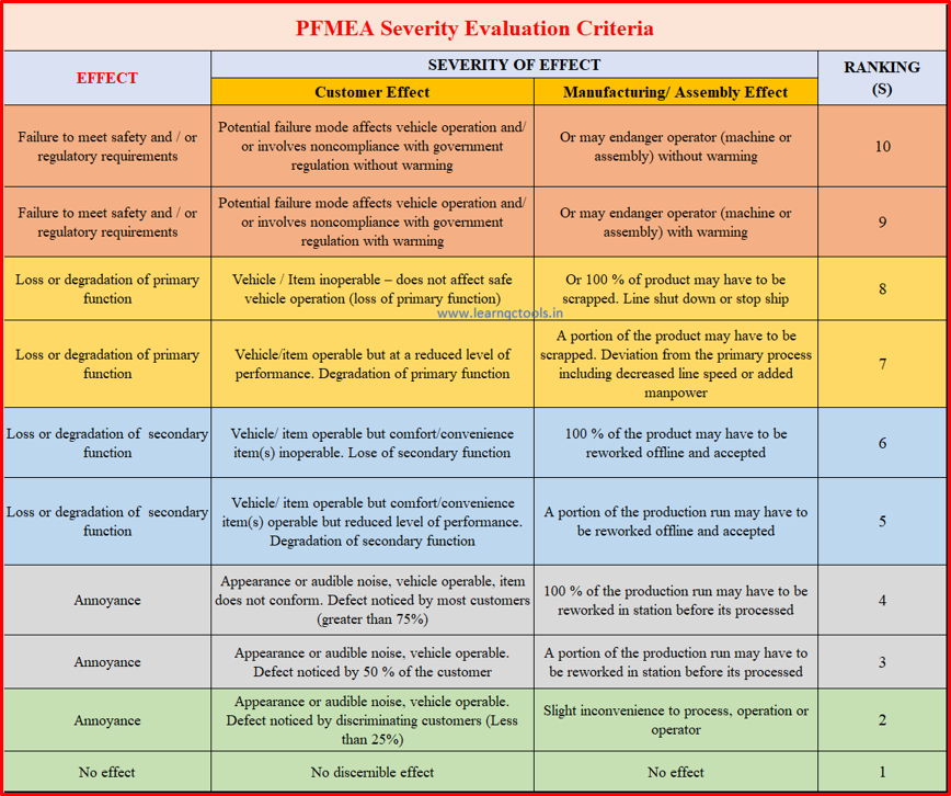
An important point is that Severity relates to the effect of the failure, not simply to the cause.
Occurrence in FMEA
Occurrence represents how frequently a failure cause or mechanism is expected to occur.
Occurrence should preferably be based on objective evidence.
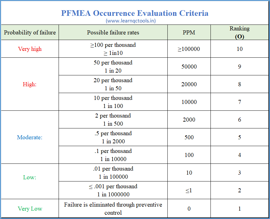
Useful information includes:
- Historical rejection data
- Customer complaints
- Warranty data
- Process capability
- Similar process data
- Defect trends
- Production records
For example, if historical data shows repeated defects caused by tool wear, that information should be considered when determining the occurrence rating.
Detection in FMEA
Detection evaluates the effectiveness of existing controls in detecting a failure or its cause according to the applicable FMEA methodology.
Examples of detection controls include:
- Visual inspection
- Vernier inspection
- Go/No-Go gauge
- Automated inspection
- Sensor
- Functional testing
- SPC monitoring
- Camera inspection
- Measurement system
However, organizations should not depend only on detection.
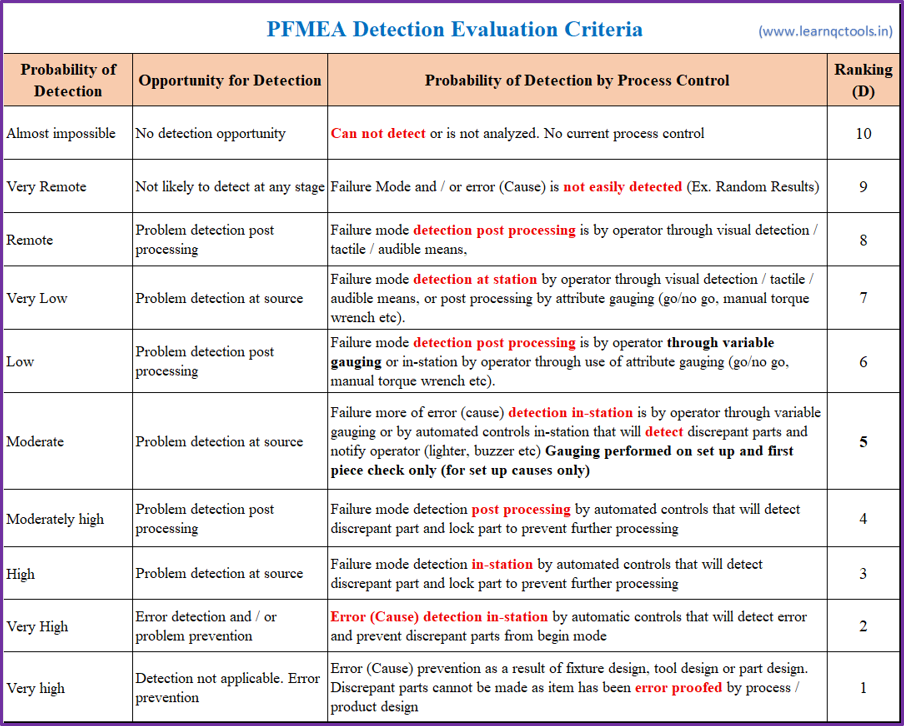
Whenever practical, the team should identify opportunities to prevent the failure.
For example, instead of relying only on final inspection to identify incorrect component orientation, a poka-yoke can prevent incorrect orientation during assembly.
Understanding Risk Prioritization
Traditional FMEA methodology commonly uses the combination of Severity, Occurrence and Detection to support risk evaluation.
Historically, this was often expressed through the Risk Priority Number (RPN):
RPN = Severity × Occurrence × Detection
For example:
Severity = 7
Occurrence = 5
Detection = 4
Therefore:
RPN = 140
However, RPN should not be treated as the only basis for deciding whether an action is necessary. High-severity failures may require attention even when their calculated RPN is not the highest.
The AIAG & VDA methodology introduced Action Priority (AP) as a structured approach to prioritizing actions. Therefore, traditional RPN-based approaches and the AIAG & VDA Action Priority methodology should not be mixed together.
For detailed information about the AIAG & VDA 7-step methodology, Action Priority and the new FMEA format, refer to your dedicated AIAG VDA Process FMEA article.
Practical PFMEA Example
Consider a CNC machining process used to manufacture an automotive component.
The process is CNC drilling and the requirement is that the hole diameter and position must meet the drawing specification.
A simplified PFMEA example is shown below.
| Process | Failure Mode | Potential Effect | Potential Cause | Prevention Control | Detection Control |
|---|---|---|---|---|---|
| CNC Drilling | Hole oversize | Assembly problem | Tool wear | Tool-life monitoring | Diameter inspection |
| CNC Drilling | Hole undersize | Assembly problem | Incorrect tool | Tool specification | Gauge inspection |
| CNC Drilling | Hole position incorrect | Assembly rejection | Fixture misalignment | Fixture poka-yoke | Position inspection |
| CNC Drilling | Burr formation | Functional/assembly problem | Incorrect cutting condition | Parameter control | Visual inspection |
This demonstrates the basic PFMEA relationship:
Process → Failure Mode → Effect → Cause → Control
The actual risk ratings should be established using the applicable FMEA methodology and relevant customer requirements.
How to Select Effective PFMEA Controls
A strong PFMEA should not simply list inspection activities.
The team should consider how failures can be prevented.
For example:
Weak approach: Inspect every component after production.
Better approach: Use a poka-yoke to prevent incorrect component loading.
Another example is torque control.
Instead of relying only on manual verification after tightening, the process could use a controlled torque tool with parameter monitoring and error-proofing.
The general principle is:
Prevent the failure whenever reasonably possible rather than depending only on detection.
PFMEA Review and Update
PFMEA should be treated as a living document.
It should be reviewed and updated when relevant information or changes can affect process risk.
Typical triggers include:
- Customer complaints
- Internal rejection
- Recurring defects
- Warranty issues
- Engineering changes
- Process changes
- New machine
- New tooling
- New material
- Supplier changes
- New inspection method
- Changes in process parameters
- New product
- New process
- Lessons learned
PFMEA should represent the actual current manufacturing process.
Horizontal Deployment of PFMEA Lessons
Suppose a problem occurs on one production line because of incorrect fixture loading.
The organization should ask:
Could the same problem occur on another machine, line, product or process?
If yes, the lesson learned should be evaluated for horizontal deployment.
Horizontal deployment helps prevent similar problems from occurring elsewhere in the organization.
For example, if a poka-yoke successfully prevents incorrect component orientation on one production line, the organization can evaluate whether similar processes require the same type of control.
Common PFMEA Mistakes:
- Preparing PFMEA only for Audit
PFMEA should be used as a practical risk-management tool, not simply as an audit document.
- Copying an Old PFMEA
Previous PFMEA information can be useful, but blindly copying it may result in missing current process risks.
- Poor Failure-Mode Descriptions
Failure modes should clearly describe what could go wrong.
- Confusing Causes and Effects
For example:
Failure Mode: Hole oversize
Effect: Assembly problem
Cause: Tool wear
- Depending only on Inspection
Inspection detects problems but may not prevent them.
- Ignoring Process Data
Actual rejection, complaint and capability data should be considered wherever available.
- Not Updating PFMEA After Changes
A changed process should be reviewed to determine whether the risk analysis remains valid.
- Poor Linkage with Control Plan
Important controls identified through PFMEA should be appropriately reflected in the Control Plan.
- No Cross-Functional Participation
PFMEA becomes more effective when people with different technical knowledge participate.
PFMEA and IATF 16949
PFMEA supports risk-based thinking and preventive quality management in automotive manufacturing.
It is closely connected with:
- Process risk analysis
- Product and process development
- Process control
- Control Plan development
- Special-characteristic management
- Lessons learned
- Manufacturing process improvement
- Customer-specific requirements
Organizations should distinguish between requirements from IATF 16949, customer-specific requirements and the methodology described in the AIAG & VDA FMEA Handbook.
For specific compliance decisions, the applicable standard and customer requirements should always be consulted.
PFMEA and Automotive Core Tools
PFMEA is closely connected with other automotive Core Tools.
A simplified relationship is:
APQP → Process Flow → PFMEA → Control Plan → Work Instructions → SPC/MSA → PPAP
PFMEA is also an important input within the PPAP process and should be consistent with the other applicable Core Tool documents.
Each tool has a different purpose.
APQP provides structured quality planning.
Process Flow defines the sequence of operations.
PFMEA identifies process risks.
Control Plan defines how important characteristics and process controls will be managed.
Work Instructions provide detailed operating instructions.
SPC helps monitor process variation.
MSA evaluates measurement-system suitability.
PPAP provides evidence that the production process can meet requirements.
Therefore, PFMEA should be developed as part of an integrated Core Tools system.
PFMEA Checklist
Before approving a PFMEA, ask:
Process
- Is the Process Flow available?
- Does PFMEA cover all relevant operations?
- Are process functions clearly defined?
Failure Analysis
- Are potential failure modes identified?
- Are effects clearly defined?
- Are causes identified?
- Are causes technically realistic?
Controls
- Are prevention controls identified?
- Are detection controls identified?
- Are important characteristics controlled?
Risk
- Are Severity ratings justified?
- Are Occurrence ratings supported by available information?
- Are Detection ratings appropriate?
- Is the correct FMEA methodology being used?
Actions
- Are improvement actions clearly defined?
- Is responsibility assigned?
- Is a target date defined?
- Is effectiveness verified?
Linkage
- Is PFMEA consistent with Process Flow?
- Is PFMEA appropriately linked to the Control Plan?
- Are lessons learned incorporated?
FMEA Occurrence Data Sheet
Historical process data can be useful when determining occurrence ratings.
An FMEA Occurrence Data Sheet can help the PFMEA team record defect history and support the evaluation of occurrence.
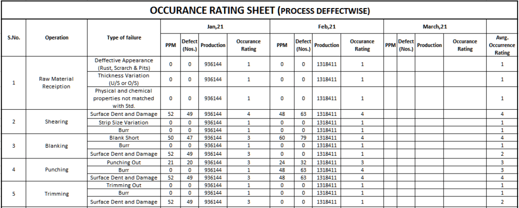
It can be useful for:
- Quality Engineers
- Process Engineers
- Production Engineers
- PFMEA teams
- Automotive suppliers
- Internal auditors
- Quality trainees
Frequently Asked Questions About FMEA
What is FMEA?
FMEA stands for Failure Mode and Effects Analysis. It is a structured method for identifying potential failures, their effects and causes and determining actions to reduce associated risks.
What is PFMEA?
PFMEA stands for Process Failure Mode and Effects Analysis. It is used to identify and manage potential failures associated with manufacturing and assembly processes.
What is the difference between FMEA and PFMEA?
FMEA is the general failure-analysis methodology, while PFMEA specifically focuses on manufacturing and process risks.
What is Severity in FMEA?
Severity represents the seriousness of the effect of a potential failure.
What is Occurrence in FMEA?
Occurrence represents the likelihood or frequency of a potential failure cause or mechanism occurring according to the applicable FMEA criteria.
What is Detection in FMEA?
Detection evaluates the ability of existing controls to detect a failure or its cause according to the applicable FMEA methodology.
What is RPN in FMEA?
RPN stands for Risk Priority Number. In traditional FMEA, it is calculated by multiplying Severity, Occurrence and Detection.
Is RPN used in AIAG & VDA FMEA?
The AIAG & VDA methodology introduced Action Priority as a structured approach for prioritizing actions rather than relying on the traditional RPN approach.
What are the 7 steps of AIAG & VDA FMEA?
The AIAG & VDA approach consists of:
- Planning and Preparation
- Structure Analysis
- Function Analysis
- Failure Analysis
- Risk Analysis
- Optimization
- Results Documentation
For a detailed explanation, refer to the dedicated AIAG VDA Process FMEA article.
What is the relationship between PFMEA and Control Plan?
PFMEA identifies potential process risks and relevant controls, while the Control Plan defines how applicable product and process characteristics will be controlled during production.
When should PFMEA be reviewed?
PFMEA should be reviewed when there are process changes, customer complaints, internal failures, engineering changes, new products, new processes, lessons learned or other information that could affect process risk.
Conclusion
FMEA is an important preventive quality tool for identifying and managing potential product and process risks before they become actual problems. In automotive manufacturing, PFMEA provides a structured approach for connecting process steps with potential failure modes, effects, causes, controls and improvement actions.
A good PFMEA should not be treated as a document created only for an audit or customer submission. It should be actively used by cross-functional teams to understand manufacturing risks, improve prevention and detection controls, capture lessons learned and support continuous improvement.
The most important principle of FMEA is simple:
Identify the risk before the failure reaches the customer, prevent the failure whenever possible, and continuously improve the process based on evidence and lessons learned.
QC Tools Solutions provides practical training and consultancy related to FMEA, PFMEA, AIAG & VDA FMEA, APQP, PPAP, Control Plan, SPC, MSA, IATF 16949 and other automotive quality-management tools.