Injection molding is one of the most widely used manufacturing processes in the automotive, electrical, electronics, and consumer goods industries. Despite advanced machines and automation, molding defects remain a major source of rejection, rework, customer complaints, and audit non-conformities. In quality systems like ISO 9001 and IATF 16949, effective control of molding defects is directly linked to product conformity, cost reduction, and customer satisfaction.
Understanding molding defects in detail, along with their root causes and practical remedies, is essential for production engineers, quality engineers, supervisors, and auditors. This article provides an in-depth explanation of all major molding defects, supported by a comprehensive table for quick reference and real shopfloor application.
What Are Molding Defects
Molding defects are deviations or imperfections in molded plastic parts that prevent them from meeting design, dimensional, functional, or aesthetic requirements. These defects may occur during any stage of the molding cycle, including material preparation, filling, packing, cooling, or ejection.
Molding defects can lead to
- High rejection and rework rates
- Customer complaints and line stoppages
- Poor appearance and reduced strength
- Audit observations during process and product audits
- Increased cost of quality (COPQ)
Classification of Molding Defects
Molding defects are generally classified into
- Filling-related defects
- Packing and cooling-related defects
- Surface and cosmetic defects
- Structural and strength-related defects
- Ejection-related defects
Each defect has specific causes linked to machine parameters, mold design, material properties, and operator practices.
Common Molding Defects with Causes and Remedies
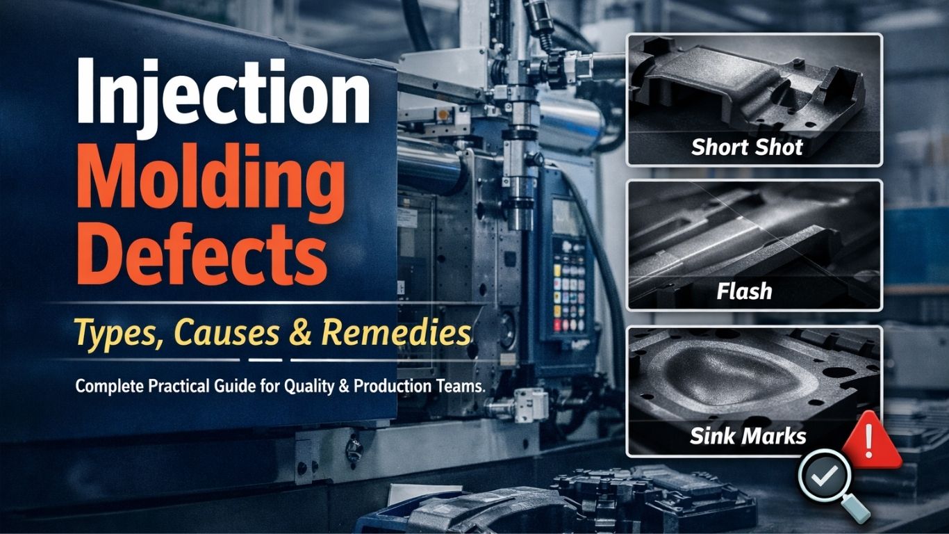
Short Shot:
A short shot occurs when molten plastic fails to fill the mold cavity, resulting in incomplete parts. This defect is commonly seen in thin sections, long flow paths, or complex geometries.
Key reasons include insufficient injection pressure, low melt temperature, inadequate shot size, blocked gates, or air entrapment.
Remedies involve increasing injection pressure and speed, raising melt and mold temperatures, ensuring correct shot size, cleaning runners and gates, and improving venting.
Flash:
Flash is excess plastic material that escapes from the mold cavity and solidifies along parting lines, ejector pins, or vents. Although flash may seem cosmetic, it often indicates serious mold or process issues.
Common causes include excessive injection pressure, insufficient clamping force, worn mold surfaces, or high melt temperature.
Remedies include optimizing injection pressure, increasing clamping force, repairing mold parting surfaces, and maintaining correct processing temperatures.
Sink Marks:
Sink marks are depressions or dents that appear on the surface of molded parts, usually near thick sections or ribs. They occur due to material shrinkage during cooling.
Root causes include insufficient packing pressure, short holding time, thick wall sections, and poor cooling design.
Remedies involve increasing holding pressure and time, optimizing part design for uniform wall thickness, improving cooling channels, and selecting low-shrinkage materials.
Warping
Warping is the distortion or bending of molded parts after ejection, resulting in dimensional instability and assembly issues.
This defect is mainly caused by uneven cooling, residual stresses, non-uniform wall thickness, or inconsistent mold temperature.
Remedies include ensuring uniform cooling, optimizing cooling time, maintaining consistent mold temperature, and balancing part geometry.
Burn Marks
Burn marks appear as black or brown discoloration on the molded part, typically at the end of flow paths. They are caused by compressed air overheating during the filling process.
Major causes include trapped air, high injection speed, poor venting, and excessive melt temperature. Remedies include improving venting, reducing injection speed, lowering melt temperature, and optimizing gate location.
Weld Lines (Knit Lines)
Weld lines occur where two or more molten plastic flow fronts meet but fail to fuse completely. These lines weaken the part and are critical in load-bearing applications.
Causes include low melt temperature, low injection speed, improper gate design, contamination, and poor venting. Remedies include increasing melt temperature and injection speed, improving gate location, ensuring material cleanliness, and enhancing venting.
Flow Marks:
Flow marks appear as streaks or wave-like patterns on the surface of molded parts, often affecting aesthetics.
They are caused by inconsistent injection speed, low mold temperature, or material viscosity variation. Remedies include stabilizing injection speed, increasing mold temperature, and improving material handling.
Jetting:
Jetting occurs when molten plastic enters the mold cavity at high speed, forming snake-like patterns instead of uniform flow.
This defect is caused by excessive injection speed, poor gate design, and low mold temperature. Remedies include reducing initial injection speed, modifying gate design, and increasing mold temperature.
Voids
Voids are internal air pockets or bubbles trapped inside molded parts. They may not be visible externally but significantly reduce strength.
Causes include insufficient packing pressure, thick wall sections, high shrinkage, and moisture in the material. Remedies involve increasing packing pressure, reducing wall thickness, ensuring proper drying, and improving cooling.
Silver Streaks (Splay)
Silver streaks appear as shiny lines or streaks on the surface and are often caused by moisture or gas in the material.
Causes include inadequate material drying, volatile gases, and excessive injection speed. Remedies include proper material drying, reducing injection speed, improving venting, and lowering melt temperature.
Black Specks
Black specks are small dark spots on molded parts caused by degraded material or contamination.
They result from material overheating, dirty barrels or hoppers, long residence time, or poor housekeeping. Remedies include regular cleaning, controlling processing temperatures, reducing residence time, and improving material handling.
Delamination
Delamination appears as layer separation or peeling on the surface of molded parts.
It is caused by material incompatibility, contamination, excessive mold release agents, or low melt temperature. Remedies include using compatible materials, minimizing mold release, increasing melt temperature, and improving mixing.
Molding Defects, Causes, and Remedies
| Molding Defect | Description | Common Causes | Remedies |
|---|---|---|---|
| Short Shot | Incomplete filling of the mold cavity | Low injection pressure, low melt temperature, blocked gates and air traps | Increase injection pressure and speed, raise temperatures, clean gates and improve venting |
| Flash | Excess material at the parting line | High injection pressure, low clamping force, worn mold | Reduce pressure, increase clamp force, repair mold |
| Sink Marks | Surface depressions | Insufficient packing, thick sections and shrinkage | Increase holding pressure/time, redesign wall thickness |
| Warping | Part distortion after ejection | Uneven cooling, residual stress | Improve cooling uniformity, optimize mold temperature |
| Burn Marks | Black or brown discoloration | Trapped air, high speed, poor venting | Improve venting, reduce speed, lower temperature |
| Weld Lines | Weak lines where flows meet | Low melt temperature, poor gate design | Increase temperature, optimize gates, improve venting |
| Flow Marks | Surface streaks | Inconsistent flow, low mold temperature | Stabilize speed, increase mold temperature |
| Jetting | Snake-like flow patterns | High injection speed, poor gate design | Reduce speed, modify gate, raise mold temperature |
| Voids | Internal air pockets | Low packing pressure, thick walls | Increase packing, reduce thickness, dry material |
| Silver Streaks | Shiny surface lines | Moisture, gas formation | Dry material, improve venting, reduce speed |
| Black Specks | Dark contamination spots | Material degradation, dirty barrel | Clean equipment, control temperature |
| Delamination | Layer separation | Contamination, low melt temperature | Use clean compatible material, raise the temperature |
Role of PFMEA and Control Plan in Reducing Molding Defects
- In automotive and IATF 16949 environments, molding defects must be systematically controlled using PFMEA and Control Plans. Each critical defect should be linked to
- Severity based on customer impact
- Occurrence based on historical rejection data
- Detection based on inspection and process controls
Control Plans should clearly define
- Critical process parameters
- Monitoring frequency
- Reaction plans in case of deviation
- Responsibilities of operators and supervisors
Using SPC on injection pressure, melt temperature, cycle time, and part weight significantly reduces defect occurrence.
Audit Perspective on Molding Defects
During process audits and customer audits, auditors typically check
- Defect trend analysis
- Corrective action effectiveness
- Linkage between PFMEA, Control Plan, and actual shopfloor controls
- Operator awareness of defect causes and remedies
Well-documented defect control strengthens audit performance and customer confidence.
Conclusion
Molding defects are not random problems but clear indicators of process instability, design weaknesses, or inadequate control systems. By understanding molding defects in detail and applying structured remedies, organizations can significantly reduce rejection, improve productivity, and meet stringent customer requirements.
A strong focus on defect prevention rather than defect detection transforms injection molding from a reactive operation into a stable and capable process.